Left and Right Multiplication of Rotations
Zhijian Qiao
1. Introduction
Left and right multiplication of rotations can be confusing when you first encounter them. I once found two different expressions for a rotation about the z-axis in a book. As I kept learning, I also found that rotations have different physical meanings and representations across fields, and even across applications within the same field. There is no need to worry too much, though: once we understand the problem itself, the confusion may disappear. To make sense of left and right multiplication, we first need to be clear about how a rotation is defined and what it means physically.
There are many ways to represent a rotation: rotation matrices, Euler angles, quaternions, axis-angle, the Lie group $SO(n)$, and its Lie algebra $so(n)$. Rotations also appear in many applications, including inertial navigation and robotics (manipulator kinematics, drone attitude estimation, SLAM, and so on). Here I use rotation matrices to explain the different cases of left and right multiplication, then use the results to interpret Euler angles.
2. Background
First, define the rotation matrices about the x-, y-, and z-axes:
\[\boldsymbol{R}_{x}(\gamma)=\left[\begin{array}{ccc} 1 & 0 & 0 \\ 0 & \cos \gamma & -\sin \gamma \\ 0 & \sin \gamma & \cos \gamma \end{array}\right]\] \[\boldsymbol{R}_{y}(\beta)=\left[\begin{array}{ccc} \cos \beta & 0 & \sin \beta \\ 0 & 1 & 0 \\ -\sin \beta & 0 & \cos \beta \end{array}\right]\] \[\boldsymbol{R}_{z}(\alpha)=\left[\begin{array}{ccc} \cos \alpha & -\sin \alpha & 0 \\ \sin \alpha & \cos \alpha & 0 \\ 0 & 0 & 1 \end{array}\right]\]The positive direction of each angle follows the right-hand rule. Notice that for rotation about the Y-axis, the $-\sin$ term is in the lower left.
Different books and library functions (including MATLAB’s makehgtform and angle2dcm) use different conventions for these matrices. We choose the convention above because of its physical meaning.
Take rotation about the z-axis as an example.
2.1 Rotating a coordinate frame
This interpretation appears in applications such as SLAM and manipulator kinematics.
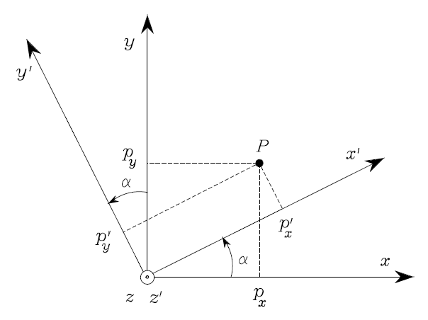
Rotation of a coordinate frame. Figure reproduced from the textbook illustration used in the Chinese original; the original post does not name the textbook.
As shown above, point $P$ stays fixed while frame $O-xyz$ rotates by $\alpha$ to become $O-x’y’z’$. In the new frame, the point has coordinates $P’$, and
\[P=\boldsymbol{R}_{z}(\alpha)P'.\]2.2 Rotating a vector
This interpretation appears, for example, in robot attitude estimation.
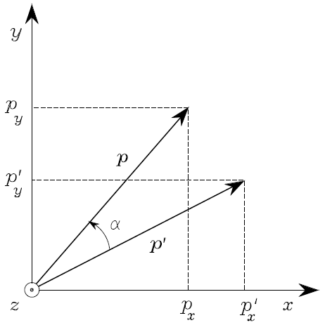
Rotation of a vector. Figure reproduced from the textbook illustration used in the Chinese original; the original post does not name the textbook.
Here frame $O-xyz$ stays fixed (it is the fixed or world frame), while point $P’$ rotates by $\alpha$ to reach $P$. I would have preferred to write this in the opposite direction, but I used the illustration from the textbook. We have
\[P=\boldsymbol{R}_{z}(\alpha)P'.\]Yes, the two equations have the same form. With this convention for rotation matrices, the two physical interpretations are consistent, which is why we use it here.
3. Right multiplication for frame rotations: rotation about body axes
For simplicity, we will no longer write each matrix in terms of rotations about x, y, and z. Consider frames 0, 1, and 2:
- $R_1^0$ is the rotation of frame 1 relative to frame 0.
- $R_2^1$ is the rotation of frame 2 relative to frame 1.
- $R_2^0$ is the rotation of frame 2 relative to frame 0.
A rotation relative to a frame is a rotation about that frame’s axes. Let $p^0$, $p^1$, and $p^2$ be the coordinates of point $p$ in frames 0, 1, and 2, respectively. From the first physical interpretation above,
\[p^{1}=R_{2}^{1}p^{2} \tag{1}\] \[p^{0}=R_{1}^{0}p^{1} \tag{2}\] \[p^{0}=R_{2}^{0}p^{2}. \tag{3}\]Combining (1), (2), and (3) gives
\[\boldsymbol{R}_{2}^{0}=\boldsymbol{R}_{1}^{0}\boldsymbol{R}_{2}^{1}. \tag{4}\]Thus, for successive rotations about the body frame’s axes, the rotation matrices are multiplied on the right in the order of rotation.
4. Left multiplication for frame rotations: rotation about fixed axes
Before deriving a relation like (4), let us see how the same rotation is represented in different frames. Suppose points $M$ and $N$ are expressed in frame 0, and $\bar M$ and $\bar N$ are their coordinates in frame 1. Assume the transformation between them contains only rotation. Using notation analogous to the above,
\[M = R_{n}^{m}N \tag{5}\] \[\bar M=\bar R_{n}^{m}\bar N \tag{6}\] \[M = R_{1}^{0}\bar M \tag{7}\] \[N = R_{1}^{0}\bar N. \tag{8}\]Substituting (7) and (8) into (5) gives
\[R_{1}^{0}\bar M = R_{n}^{m}R_{1}^{0}\bar N. \tag{9}\]From (9), we obtain the relation we need:
\[R_{n}^{m} = R_{1}^{0}\bar R_{n}^{m}R_{0}^{1}. \tag{10}\]This equation shows how the same rotation, taking $N$ to $M$, is represented in two frames, 0 and 1. With that result in hand, we can get back to the main question.
Again consider frames 0, 1, and 2, with frame 0 fixed. These frames are separate from the frames 0 and 1 used just above. A rotation is a physical event; a rotation matrix is a tool for describing it. We use the following notation:
- $\bar R_1^0$ represents, in the fixed frame, the rotation of frame 1 relative to frame 0.
- $\bar R_2^1$ represents, in the fixed frame, the rotation of frame 2 relative to frame 1.
- $\bar R_2^0$ represents, in the fixed frame, the rotation of frame 2 relative to frame 0.
From (10) and the definition of frame 0 as the fixed frame,
\[\bar R_1^0 = R_1^0 \tag{11}\] \[\bar R_2^0 = R_2^0 \tag{12}\] \[\bar R_2^1 = R_{1}^{0}R_2^1R_{0}^{1}. \tag{13}\]To see how (13) follows from (10), $R_2^1$ represents the rotation in frame 1 and corresponds to $\bar R_n^m$. Meanwhile, $\bar R_2^1$ represents it in the fixed frame (frame 0) and corresponds to $R_n^m$. The change of representation depends on $R_1^0$, the rotation of frame 1 relative to frame 0.
Substituting (11)–(13) into (4) gives
\[\bar R_2^0 = R_1^0R_0^1\bar R_2^1R_{1}^{0} = \bar R_2^1\bar R_{1}^{0}. \tag{14}\]Thus, for rotations about the fixed frame’s axes, the rotation matrices are multiplied on the left in the order of rotation.
5. Left multiplication for vector rotations
In a fixed frame, rotate point $p_0$ to $p_1$ using $R_0^1$, then rotate $p_1$ to $p_2$ using $R_1^2$. We can also take $p_0$ directly to $p_2$ with $R_0^2$. Then
\[p_1 = R_0^1p_0 \tag{15}\] \[p_2 = R_1^2p_1 \tag{16}\] \[p_2 = R_0^2p_0. \tag{17}\]It follows that
\[R_0^2 = R_1^2R_0^1. \tag{18}\]6. Right multiplication for vector rotations
There is not much to explain here. In this physical interpretation, the vector rotates with respect to the fixed frame, so the rotations are left-multiplied.
7. Euler angles
A common Euler-angle order in robotics is ZYX. The three angles are called yaw, pitch, and roll, respectively:
\[\begin{aligned} R(\alpha, \beta, \gamma)&=R_z(\alpha) R_y(\beta) R_x(\gamma)\\ &=\left(\begin{array}{ccc} \cos \alpha \cos \beta & \cos \alpha \sin \beta \sin \gamma-\sin \alpha \cos \gamma & \cos \alpha \sin \beta \cos \gamma+\sin \alpha \sin \gamma \\ \sin \alpha \cos \beta & \sin \alpha \sin \beta \sin \gamma+\cos \alpha \cos \gamma & \sin \alpha \sin \beta \cos \gamma-\cos \alpha \sin \gamma \\ -\sin \beta & \cos \beta \sin \gamma & \cos \beta \cos \gamma \end{array}\right). \end{aligned}\]We can view this matrix as the robot’s attitude in the fixed frame. To obtain the same matrix (and attitude), we can either:
- Rotate about the fixed X-axis, then the fixed Y-axis, then the fixed Z-axis.
- Rotate about the body Z-axis, then the body Y-axis, then the body X-axis. Initially, the body and fixed frames coincide.
One thing to keep in mind: a given Euler-angle order and set of angles determines one rotation matrix, but the same rotation matrix can have different Euler angles under different orders. Even with the same order, different angles can produce the same matrix. For example, when pitch $\beta$ is 90°, there is a singularity:
\[\begin{aligned} R(\alpha, \tfrac{\pi}{2}, \gamma)&=R_z(\alpha)R_y(\tfrac{\pi}{2})R_x(\gamma)\\ &=\left(\begin{array}{ccc} 0 & \sin(\gamma-\alpha) & \cos(\gamma-\alpha) \\ 0 & \cos(\gamma-\alpha) & -\sin(\gamma-\alpha) \\ -1 & 0 & 0 \end{array}\right). \end{aligned}\]As long as the difference between yaw $\alpha$ and roll $\gamma$ remains the same, infinitely many ZYX body-axis Euler angles produce this rotation matrix. See gimbal lock for the related discussion.
8. A final note
When working with rotations, keep two things straight:
- What is the physical meaning? Is it a rotation of a frame or a vector, and which point is transformed into which?
- Is the notation consistent? Know what each superscript and subscript means, and connect it to the physical interpretation.